
ETC is authorized provider of Electrical Installation’s Study, Analysis, Inspection, and Certification services in UAE, and offer unbalanced load flow study and analysis services.
Load flow analysis is an important function for power system planning and practical studies. Certain applications, particularly in distribution automation and optimization of a power system, require repeated load flow solution and in these applications, it is very important to solve the load flow problem as efficiently as possible.
As the power distribution networks become more complex, there is greater demand for efficient and reliable system operation. Consequently, the most important system analysis tool, load flow studies, should be capable of handling various system configurations with adequate accuracy and speed.
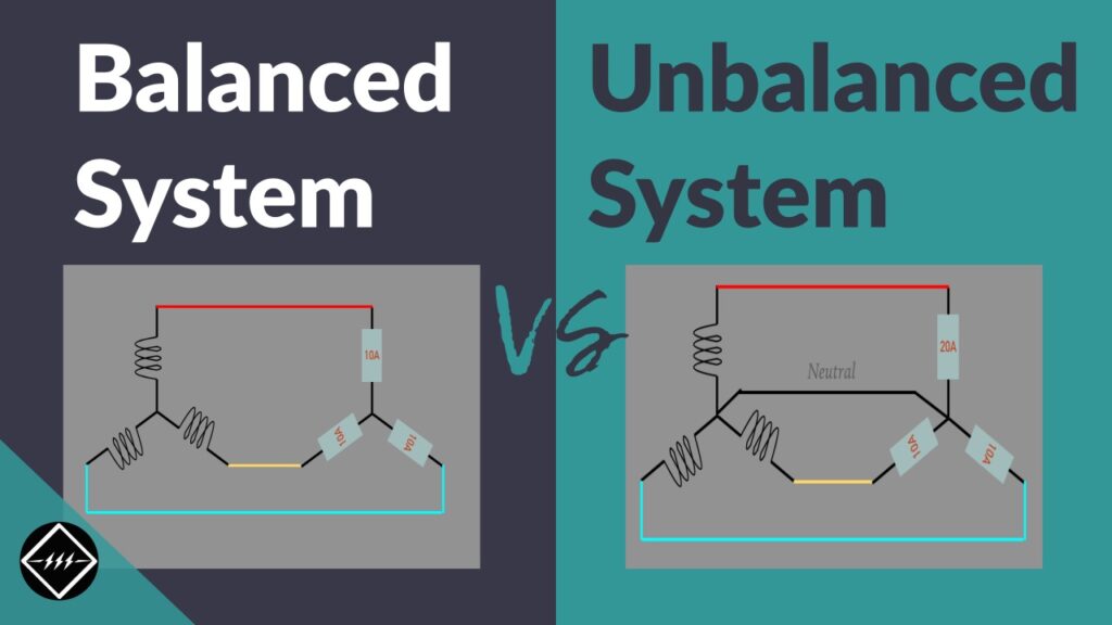
In several situations, it observed that the radial distribution systems remain unbalanced due to single-phase, two-phase and three-phase loads. Thus, load flow solution for unbalanced case, special analysis is necessary.
Usual load flow method cannot directly apply to distribution systems. The mode used for three phase power flow analysis in unbalanced systems cannot develop by extending the single phase balanced methods. A three-phase load flow method has to analyze problems like modeling of different forms of fundamental connections that would regulate starting point for three phase power flow solution as there are phase shifts and transformation ratios for each phase and at different buses. For un-transposed lines and cables the balanced models are no longer useful.
The symmetrical component transformation can decouple the three phases. For three phase networks burden matrix obtain. A method to measure power losses in unbalanced radial distribution systems.
How to Model the Transformer for Power Flow Analysis.
Fast Decoupled Power Flow Method for Unbalanced Radial Distribution Systems
This method prefers the laterals instead of buses into layers, it would decrease the problem size to the number of laterals. Using lateral variable rather than bus variable makes this methods adequate for given system topology, however it may add some obstacle if the network topology changed frequently, which is common in distribution systems because of switching operations. Finding three-phase radial distribution networks. This method uses the forward and backward propagation to measure branch currents and bus voltages.
The three-phase Current Injection Method, injection equations written in rectangular regulates full Newton method. Also it shows quadratic convergence properties and convergence obtained for all except some conditioned cases. This uses G-matrix for power flow based on equal current injections. The Network Topology which uses two matrices, viz. Bus Injection to Branch Current and Branch-Current to Bus-Voltage matrices, to find out the solution, modeling of transformer and other components of distribution systems, load flow solution of unbalanced radical distribution networks.
Improved load flow method for unbalanced Radical Distribution System using sequence components. The different connections of transformer in as unbalanced radial distribution networks. Three phase load flow method by solving algebraic recursive expression of voltage significance.
Load Flow Solution of Unbalanced Radial Distribution Networks
Efficient method for load flow analysis plays an important role in automation algorithms of Radical Distribution System whose scope encloses fault isolation, network reconfiguration and service restoration. Automation algorithm is capable of handling these complex tasks that need frequent topological variations in the Radical Distribution System which demands a dynamic topology processor based on a well-defined data structure.
Unbalanced Radial Distribution System
Unbalanced radial distribution system can be modeled as a network of buses connected by distribution lines, switches or transformers. Each bus may have a corresponding load, shunt capacitor and co-generator connected to it. This model represented by a radial interconnection of copies of the usual building block for the analysis of power transmission line, two fundamental assumptions made, namely:
Three-phase Currents Balanced
Transposition of the conductors to get balanced line parameters. However, distribution systems do not give themselves to either of the two assumptions. Due to dominance of single-phase loads, the assumptions of balanced three-phase currents are not applicable. Distribution lines are hardly changed, nor can it be assumed that the conductor configuration is an equilateral triangle. When two assumptions are invalid, it is necessary to introduce another proper method of calculating the line obstruction.
Lumped Load
In distribution systems loads exist in one, two and three phase loads with delta connections. Also loads can differentiated into four types depending on the load characteristics like constant power, constant impedance, constant current and complex loads. In this chapter, the loads considered as constant power type and can mathematically represented as follows
Distributed Load
At times the primary feeder supplies loads through distribution transformers tapped at various locations along line section. If each load point modeled as a bus topology, there will be large number of bus topology in the system. Hence these loads represented as lumped loads:
The remaining one-third load assumed to connect at the receiving end bus.
At one-fourth length of line from sending a dummy bus created at which two third of the load assumed to connect.
Transformer
The impact of the transformers in a distribution system is significant. Transformers affect system loss, <span”>zero sequence current, method of grounding and protection strategy.
Core Loss
The core loss of a transformer approximated by shunt core loss functions on each phase of the secondary terminal of the transformer. These core loss approximation functions based on the results of load modeling analysis which analyze that real and reactive power loss in the transformer core can express as functions of the terminal voltage of the transformer. Transformer core loss functions represented in per unit at the system power base.
VOLTAGE DROP STUDY AND ANALYSIS
In an electric circuit the existing energy of a voltage supply decreases as electric current travels through the components that does not supply voltage i.e. passive elements of an electrical circuit. This is called Voltage Drop. Each point in a circuit can be assigned a voltage that’s proportional to its electrical elevation, so to speak. Voltage drop is simply the arithmetical difference between a higher voltage and a lower one. The National Electrical Code states that a voltage drop of 5% at the furthest receptacle in a branch wiring circuit is acceptable for normal efficiency
Why Perform Voltage Drop Study and Analysis?
Following are the harm caused by extensive voltage drop:
- Low voltage to the equipment being powered, causing improper, erratic, or no operation – and damage to the equipment.
- Poor efficiency and wasted energy.
- Heating at a high resistance connection/splice may result in a fire at high ampere loads.
One cannot determine exactly at what point voltage drop can cause fire, because it varies with the amount of current flowing through the high resistance connection, the resistance of that connection etc. Number of factors must be considered regarding at what point ignition will occur, example:
- Is the high resistance connection in connection with a flammable matter?
- Is there air flow to dissipate the heat?
- Is the area around the connection insulated, so that heat cannot escape?
Voltage drop study and analysis must be taken into consideration so that it may hardly affect the instruments. Like some household appliances that have a fixed capacity power engines are strongly influenced by voltage drop.
The main ways to reduce voltage drop are to:
- Increase power factor (add capacitors)
- Replace the conductor with a larger size.
What is Done During Voltage Drop Study and Analysis?
The reduction of any rate in the voltage leads to a rise in the current at the same rate and the problem is that this increase is often not huge. If we assume that this increase in the current was by 11%, it means that circuit breaker will not feel this increase and it will not operate while the device suffers from this increase in the current and thus leading to the increase in temperature gradually with time until it reaches the stage of the combustion. Another example the voltage drop by 1% lead to decrease in illuminance of tungsten lamp by 3%.
The amount of power delivered to a component in a circuit is equal to the voltage drop across that component’s terminals multiplied by the current flow through the component:
P = V*I
V = voltage drop in volts
I = current flow in amperes and
P =power in watts.
Obviously, if either V or I is zero, no power or energy is delivered to that component, so it can’t fulfil any useful purpose. So voltage drop is a vital feature of all electric circuits and is planned and controlled very carefully by the engineers that design those circuits.
So the transformers and the distribution boxes must be situated in a position such that maximum voltage drop from transformer to the furthest point doesn’t exceed 5% of the nominal voltage. lf it hard to find a place for the transformer so that maximum voltage drop is less than 5%, then we must use cables with larger cross-section area but It will increase the cost.
How is Voltage Drop Study and Analysis Done?
There are two methods by which voltage drop study and analysis can be done:
- Manual
- ETAP
Manual Voltage Drop Study and Analysis
Ohm’s Law Method – Single-Phase Only
Voltage drop of the circuit conductors is calculated by multiplying the complete resistance of the circuit conductors by the current through the circuit:
VD = I x R
I = Load in amperes
R = Resistance of the conductor
This method cannot be used for 3 phase circuits.
Voltage Drop Using the Formula Method
The voltage drop of circuit with already installed conductors can be calculated by:
VD = 2 * K * Q * I * D/CM – Single Phase
VD = 1.732 * K * Q * I * D/CM – Three Phase
VD = Volts Dropped
K = Direct Current Constant
Q = Alternating Current Adjustment Factor’
I = Amperes
D = Distance
CM = Circular-Mils
Electrical Transient Analyzer Programming (ETAP):
Since 1970s, ETAP has been a significant designing podium utilised for designing, analysing, and optimising electrical power systems. ETAP is a completely assimilated Electrical software solutions comprising of load flow, arc flash, short circuit and more. Its flexible performance makes it apt for all companies in any shape or form.
Operation Technology, Inc. is the developer of ETAP, the most wide-ranging analysis software for the simulation, design, operation, control, monitoring and automation of power systems. ETAP is the industry leader used worldwide in all types and sizes of power systems such as manufacturing, oil and gas, steel, mining, cement, and more.
We can approximate the voltage drop along a circuit as:
Vdrop= |Vs| – |Vr| ≈ IR·R + IX·X
Where, Vdrop= voltage drop along the feeder
R= line resistance
X= line reactance
IR= line current due to real power flow (in phase with the voltage)
IX= line current due to reactive power flow (90°out of phase with the voltage)
The biggest fault happens under leading power factor and heavy current. The approximation has an error less than 1% for an angle between the sending and receiving end voltages.
This estimation brings two crucial factors about voltage drop into the light:
Resistive load: At large power factors, the voltage drop is related directly to the resistance of the conductors. The resistance plays a crucial role, even though the resistance is generally less than the reactance.
Reactive load: At medium or small power factors, the voltage drop relates mostly to the reactance of the conductors. Because the reactance is usually larger than the resistance, the reactive load causes most of the voltage drop. Poor power factor significantly increases voltage drop.
ETC is authorized provider of Electrical Installation’s Study, Analysis, Inspection, and Certification services in UAE, and offer voltage drop study and analysis services.